Geometry Specification
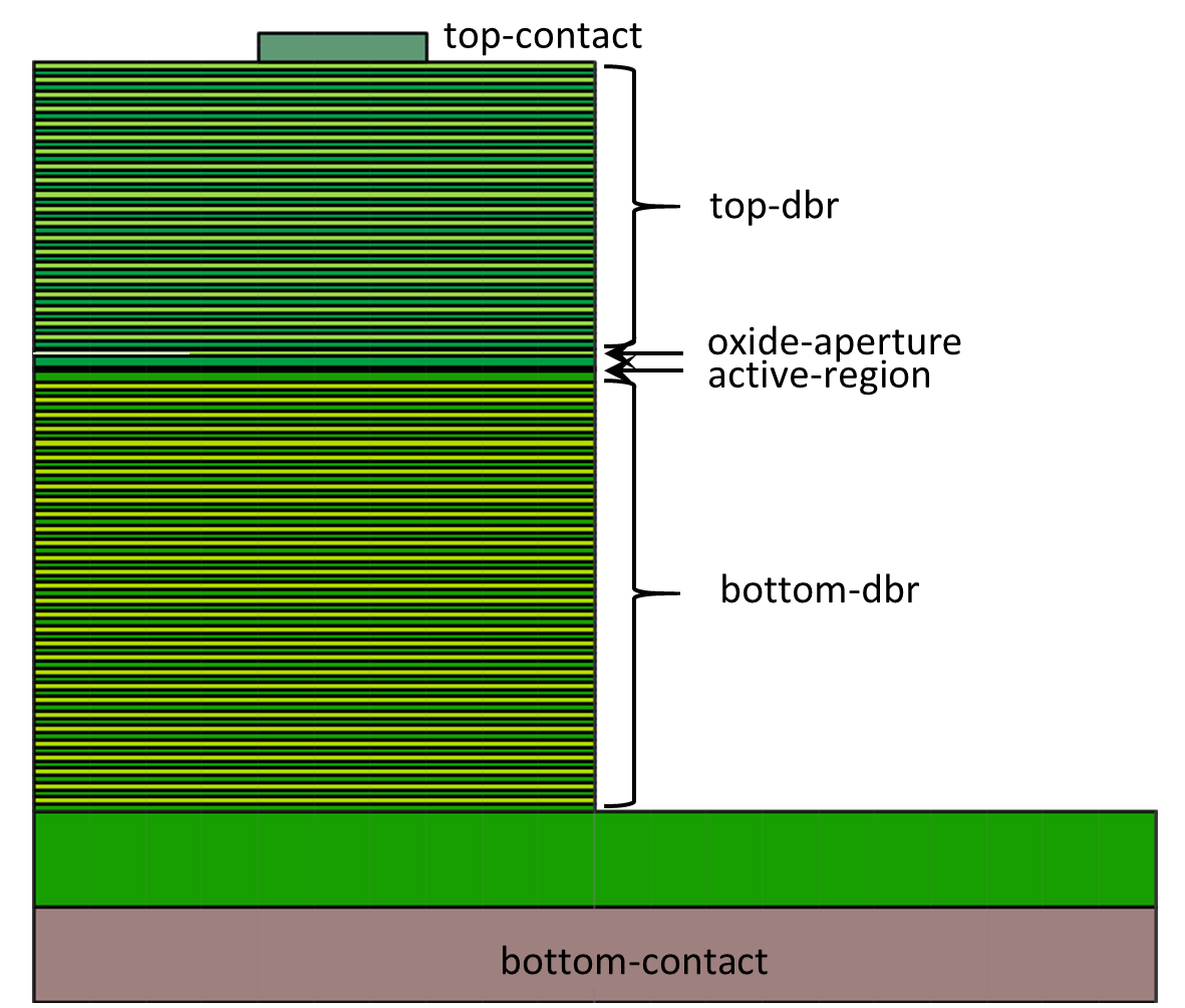
The whole definition of the structure’s geometry is based on the geometry tree. Every physical object is defined as a leaf of this tree. Below is a simple example of VCSEL two-dimensional cylindrical geometry in the xpl script form:
<cylindrical2d name="main" axes="r,z">
 <!-- This is comment not visible by the solver -->

 <stack>
 <!-- "<stack>" places physical objects one on the other; a whole geometry of
 the laser must be defined as a stack -->

  <shelf>
       <gap total="7"/>
       <block dr="3" dz="0.3" name="top-contact" material="AuGe" />
       <!-- This is physical object (here, in a 2D cylindrical geometry:
       a disc or ring) of 3um radius and 0.3um height -->
  </shelf> <!-- This describes the end of the shelf definition -->

  <!-- To make a contact on a side of the structure one have to use the
  "<shelf>" which presents the physical objects placed one beside the other
  like books on a shelf. "<gap>" fills the missing places with air -->

  <stack name="top-dbr" repeat="20">
  <!-- "repeat" defines the repetitions of stacks -->
       <block dr="10" dz="0.0795" material="Al(0.73)GaAs:Si=2e+18"/>
       <!-- A lot of materials are defined in the database of the PLaSK,
       here "0.73" defines the fraction of the aluminium in AlGaAs and
       "Si=2e+18" defines the dopant and doping level of this material -->
       <block dr="10" dz="0.07" material="GaAs:Si=2e+18"/>
  </stack>

  <shelf name="oxide-aperture">
       <block dr="3" dz="0.0160" name="aperture" material="AlAs:Si=2e+18"/>
       <block dr="7" dz="0.0160" name="oxide" material="AlOx"/>
  </shelf>

  <block dr="10" dz="0.0635" material="Al(0.73)GaAs:Si=2e+18"/>
  <block dr="10" dz="0.1160" material="GaAs:Si=5e+17"/>

  <stack name="active-region" role="active">
  <!-- "role="active"" is here necessary for the solver to know where
  the active region is; "role="QW"" below is necessary as well-->
       <stack repeat="4">
        <block dr="10" dz="0.0060" material="GaAs" name="barrier"/>
        <block dr="10" dz="0.0040" name="QW" role="QW" material="InGaAsQW"/>
       </stack>
       <again ref="barrier"/>
       <!-- This command is used to refer and to place the geometry
       object "barrier" which was defined earlier in the script-->
  </stack>

  <block dr="10" dz="0.1160" material="GaAs:C=5e+17"/>

  <stack name="bottom-DBR" repeat="30">
       <block dr="10" dz="0.0795" material="Al(0.73)GaAs:C=2e+18"/>
       <block dr="10" dz="0.0700" material="GaAs:C=2e+18" />
  </stack>

  <zero/>
  <!-- This command defines the vertical zero position;
  all objects above are z>=0 and below z<0 -->

  <block material="GaAs:C=2e+18" dr="20." dz="1."/>
  <!-- This substrate is thin only for clear presentation reasons,
  same as a copper heat sink below -->
  <block name="bottom-contact" material="Cu" dr="20." dz="1."/>
  <!-- Names for contacts are necessary for future reference -->
 </stack>
</cylindrical2d> <!-- The end of this geometry definition -->
This geometry defines such a structure:
Into newly defined geometry various items can be included (press + symbol in the top left corner of the program and select the item tag):
containers are branches of the tree which include leafs. I.e. containers are boxes in which physical objects are placed. Containers are:
align
shelf (only in 2d geometry)
stack
For their attributes see section Containers 2D or Containers 3D.
transforms - transforms always contain a single geometry object (possibly a container) as their content and perform some transformation of this object. Transforms are:
arrange
clip
flip
intersection
mirror
translation
extrusion (only in 3d geometry)
lattice (only in 3d geometry)
revolution (only in 3d geometry)
For their attributes see section Transforms 2D or Transforms 3D.
physical objects which are the leafs of the whole geometry tree. Physical geometry objects are representing actual objects having defined shape, dimensions and material. One can define following physical objects for two-dimensional geometry:
Rectangular block. Its origin is located at the lower left corner.
Triangle with one vertex at point (0, 0).
Circle with centre at point (0, 0).
or these for three-dimensional geometry:
Rectangular block. Its origin is located at the lower back left corner.
Cylinder with its base lying in the horizontal plane. Its origin is located at the center of the lower circular base.
Sphere with centre at point (0, 0, 0).
For their attributes see section Physical objects 2D or Physical objects 3D.
Each geometry object can have an optional name for further reference in computational script or further in geometry specification. Each geometry object can therefore be copied - see section Copies and references to geometry objects.
After selecting the type of the physical object its dimensions and material must be defined.
To build a whole laser you just have to add physical object one on another (using stack container) or one beside the other (using shelf container).
Specifying geometry in XPL file
See Section <geometry>.
Creating Geometry from Python
See section plask.geometry.
Reference of Geometry Objects
See sections Section <geometry> and plask.geometry.